
close
Choose Your Site
Global
Social Media


Views: 0 Author: Site Editor Publish Time: 2026-05-25 Origin: Site


Upgrading vehicle charging capabilities often introduces severe weight, space, and thermal penalties. Engineers face constant pressure balancing fast recharge times against strict physical chassis limits. For compact frames and highly specialized applications, over-specifying an On-Board Charger (OBC) leads rapidly to diminishing returns and packaging failures. Bulky charging hardware eats into precious payload capacity and demands heavy cooling systems you simply cannot afford in smaller vehicles.
Fortunately, the 3.3kW OBC serves as the optimal engineering baseline where absolute physical constraints dictate design. It perfectly balances acceptable AC charging times against strict payload and thermal management requirements. You can achieve reliable overnight or mid-shift charging without compromising vehicle dynamics.
In this guide, we provide technical procurement teams and electrical engineers a comprehensive evaluation framework. You will discover exactly how to integrate these chargers across varied form factors—ranging from urban micromobility to harsh marine environments. We focus heavily on modern component topology, rigorous environmental resilience, and real-world integration realities.
Upsizing OBC capacity historically adds 5–8kg per kW; a 3.3kW unit preserves critical payload margins in compact mobility and marine applications.
Modern 3.3kW chargers utilize Wide Bandgap (WBG) materials like Silicon Carbide (SiC) and Phase-Shifted Full-Bridge (PSFB) or LLC topologies to hit >94% peak efficiency.
Environmental compliance—specifically IP67 full-sealed potting—is a non-negotiable evaluation criterion when transitioning from road use to electric marine deployments.
Implementing a 3.3kW fan cooled OBC for 2W/3W requires rigorous ambient temperature testing, as engine bay environments can frequently exceed standard operational thresholds.
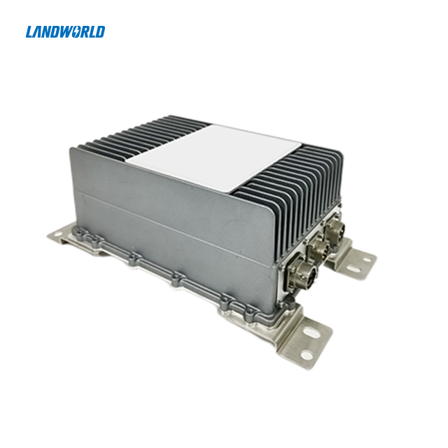
Engineers know onboard AC-to-DC conversion faces strict physical limits. You cannot easily cheat physics or ignore material densities. Upsizing a charger historically adds roughly five to eight kilograms per kilowatt of capacity. Heavy passenger vehicles often bypass the internal OBC entirely by relying on external DC fast chargers. However, built-in AC charging remains strictly mandatory for daily operational flexibility. Drivers need the ability to plug into standard municipal grid outlets everywhere. A properly sized 3.3kW unit represents the ideal compromise.
Consider the thermal footprint involved in power conversion. A 3.3kW power draw aligns perfectly against the natural heat dissipation limits of compact vehicles. High-capacity charging generates immense heat, necessitating complex cooling infrastructure. By restricting the AC input to 3.3kW, you prevent the need for heavy, active liquid-cooling loops in smaller chassis. You keep the overall design remarkably simple, highly reliable, and exceptionally lightweight.
Furthermore, a 3.3kW output creates excellent battery system synergy. It matches standard battery capacities found in light EVs perfectly. For example, charging a 10kWh battery at 3.3kW takes approximately three hours. This represents a gentle 0.3C charging rate. Such optimal C-rates easily support daily overnight or mid-shift charging routines. More importantly, this slower, controlled charging prevents elevated cell temperatures. You completely avoid accelerating battery degradation, preserving cell chemistry over thousands of cycles.
Operational environments dictate specific OBC configurations across different vehicle categories. Hardware must adapt fluidly to its physical surroundings. Below, we explore how specific vehicle architectures demand unique charging profiles.
A 3.3kW fan cooled OBC for 2W/3W chassis must survive intense real-world conditions. You must focus aggressively on vibration resistance and highly compact physical dimensions. In any electric 2W/3W application, every single cubic centimeter matters. Designers mount these internal chargers very close to active suspension components. They face constant mechanical shock and endless road debris. Standard consumer electronics would fail here within days.
Moving off-road changes the equation significantly. An electric construction vehicle demands extreme ruggedness. You need massive shock tolerance and absolute dust ingress protection. Heavy machinery frequently operates far away from stable infrastructure. Therefore, the onboard charger must maintain rigid electrical stability under wildly fluctuating grid inputs. Worksites often experience voltage drops when large diesel generators or heavy tools spool up. The charger firmware must handle these input variations gracefully.
Urban mobility demands highly intelligent packaging. In an A0 or A00-class electric passenger vehicle architecture, automotive engineers prioritize cabin space over hardware packaging. The 3.3kW unit tucks neatly under passenger seats or shallow floorboards. It delivers enough overnight charging speed without compromising vital legroom. Keeping the unit small reduces the overall vehicle curb weight, directly improving driving range.
Commercial fleet operators view vehicle charging differently. They deploy the electric commercial vehicle primarily for last-mile logistics routing. These delivery vans depend heavily on wide AC voltage compatibility. Urban grids often sag during peak afternoon hours. A premium charger tolerates these sags without aborting the charge cycle. This flexibility minimizes delivery downtime across varying municipal power grids. Delivery drivers plug in anywhere securely, ensuring constant route readiness for the next shift.
Water introduces entirely new engineering hazards. An electric boat faces relentless, aggressive salt-fog corrosion. It endures constant wave-induced hull vibration and requires absolute galvanic isolation. You cannot use standard, unsealed automotive enclosures in these damp conditions. Salt moisture bypasses standard gaskets easily, destroying sensitive PCB traces almost immediately.
Instead, marine engineers rely on heavily modified, fully sealed units. An IP67-rated 3.3kW OBC pairs beautifully alongside high-discharge NMC marine batteries. This optimized setup ensures highly reliable shore-power charging for any personal electric marine application. It powers electric jet skis and yacht tenders safely. Strict galvanic isolation protects human users from lethal high-voltage risks when interacting near wet docks.
Application Requirements Summary Chart
Vehicle Application |
Primary Environmental Hazard |
Critical OBC Requirement |
Recommended Topology Approach |
|---|---|---|---|
Electric 2W/3W |
Vibration & Space constraints |
Ultra-compact form factor |
High-frequency WBG switching |
Construction Machinery |
Heavy dust & Grid instability |
Wide input voltage tolerance |
Fully potted enclosure |
Light Fleet Vans |
Constant use & Routing downtime |
Fast CAN bus handshake |
Interleaved Boost PFC |
Marine Watercraft |
Salt fog & Water ingress |
IP67 galvanic isolation |
LLC Resonant Converter |
Understanding internal architecture helps procurement teams make informed decisions. Modern units feature single-phase AC/DC conversion utilizing Interleaved Boost Power Factor Correction (PFC). This specific topology offers superior power density compared to older single-switch designs. By spreading the electrical current across two parallel phases, Interleaved PFC halves the input ripple current. It shrinks the required magnetic components dramatically, allowing a much smaller physical footprint.
Next, we must assess the industry shift toward Wide Bandgap (WBG) devices. Engineers increasingly specify Silicon Carbide (SiC) or Gallium Nitride (GaN) components. These advanced semiconductor materials enable precise soft-switching techniques. Specifically, they utilize Zero Voltage Switching (ZVS) and Zero Current Switching (ZCS). These methods eliminate switching losses almost entirely. They push peak efficiencies beyond 94 percent easily. High efficiency translates directly into reduced heat generation inside the chassis.
Safety relies entirely on proper isolation standards. You must require absolute clarity from hardware vendors regarding galvanic isolation methods. Manufacturers typically achieve this critical separation via Series Resonant Converters (SRC) or sophisticated LLC networks. This isolation remains highly critical for preventing high-voltage leaks to the metal chassis or surrounding water. A robust LLC network ensures the high-voltage DC bus never physically touches the incoming AC grid line.

We must analyze the strict necessity of thermally conductive silicone potting. This thick, viscous material guarantees IP67 protection against moisture and dust. Manufacturers pour this liquid silicone over the entire PCB assembly, curing it into a solid block. It acts as a highly effective passive heat sink, transferring component heat directly to the outer aluminum shell. You will find this fully sealed approach essential for marine and heavy construction applications.
Let us address the harsh reality of engine bay thermodynamics. Referencing industry standards, such as U.S. Department of Energy (DOE) testing parameters, provides vital context. Power electronics routinely face localized ambient temperatures nearing 145°C to 150°C during peak summer operation. You must understand exactly how the internal charger manages thermal throttling. Good firmware reduces power output gracefully—perhaps dropping from 3.3kW down to 1.5kW—long before catastrophic thermal runaway occurs.
Finally, consider your cooling mechanism carefully. We offer a realistic comparison of maintenance cycles below to help guide your system design:
Fan-Cooled Units: They lower upfront engineering complexity significantly. They weigh less, making them ideal for light scooters. However, they require periodic clearing of intake pathways. Dusty environments choke small fans quickly, leading to premature thermal shutdowns.
Sealed Liquid-Cooled Units: They handle higher continuous electrical loads effortlessly. They resist external dirt perfectly because they lack open vents. Yet, they introduce complex plumbing risks and increase total system weight. You must maintain coolant levels and check for hose leaks regularly.
Passive Potted Units: They offer zero moving parts. They rely entirely on chassis contact for heat dissipation. They represent the ultimate "install and forget" solution for marine environments, though they require careful initial thermal interface mounting.
Procurement teams need clear, actionable shortlisting logic when evaluating global vendors. Hardware specifications only tell half the story. Integration success depends heavily on software compatibility and robust manufacturing quality control.
Verify Communication Protocols: You should mandate CAN bus (CAN 2.0B) support immediately. This standard ensures seamless digital handshakes between the vehicle's Battery Management System (BMS) and the external charging station (EVSE). Without robust CAN communication, the charger cannot accurately read cell voltages or adjust current limits dynamically.
Confirm Global Voltage Compatibility: Ensure the unit supports a wide AC input range, typically spanning 90 to 265VAC. This wide operational window allows vehicles to function across international municipal grids safely. You completely avoid forcing customers to carry bulky external transformers or adapters when crossing borders.
Audit the Supply Chain: Conduct thorough supply chain and reliability audits. Look far beyond the basic specification sheet. Assess vendor adherence to stringent automotive standards, such as the IATF 16949 certification. Review their end-of-life recycling considerations carefully. Always demand transparent mean-time-between-failures (MTBF) testing data before signing any long-term purchasing contract.
Following this precise framework prevents costly integration failures late in the development cycle. It ensures you source hardware capable of surviving the actual operational environment, rather than just passing a sterile laboratory bench test.
Selecting the right onboard power hardware remains an exercise in precise engineering balance. You must carefully weigh necessary charging power against strict payload limits and harsh environmental realities. The 3.3kW platform repeatedly proves itself as the most versatile baseline for compact mobility.
We recommend engineering teams thoroughly audit their thermal management capabilities first. Identify your exact environmental use cases early in the design phase. Assess whether your chassis will face marine salt water, heavy construction dust, or constant urban vibration. Clarify these details before finalizing your topology and cooling requirements. Finally, encourage your procurement staff to request customized, application-specific testing data for your unique OEM integrations.
A: Upsizing to a 6.6kW charger introduces strict weight penalties, often adding several unnecessary kilograms. Two-wheeler and three-wheeler frames possess severe physical space constraints. A 3.3kW unit perfectly matches standard battery capacities. It provides optimal overnight charging speeds while preserving vital payload capacity and balancing the chassis effectively.
A: Generally, no. While fan-cooled units work wonderfully for well-ventilated land vehicles, marine environments present distinct hazards. Boats and jet skis typically demand fully sealed, IP67-rated potted enclosures. This high protection level is absolutely necessary to survive constant salt fog exposure, extreme moisture ingress, and rapid wave impacts.
A: Silicon Carbide (SiC) technology does increase upfront component costs. However, it drastically improves peak power efficiency, frequently pushing it beyond 94 percent. This high efficiency significantly reduces internal heat generation. Consequently, you minimize your thermal management requirements, lowering total system weight and extending operational longevity.


